
A portable stress meter is useful only when its measurement route matches the glass. JF-2E uses the optical waveguide effect to measure surface stress in chemically tempered and thermally tempered glass. JF-2E is a portable version with a 3.5-inch PDA and a 4000 mAh battery. For a laboratory comparing heat-treated specimens, the thermal-glass interface is the starting point for a sample-specific evaluation.
The practical value is a local viewing and measurement arrangement with adjustable setup inputs. Choose the thermal route, establish the relevant glass properties and compare specimens under a defined routine. The chemical-glass and thermal-glass contexts should remain distinct when interpreting the outputs.
The portable configuration and measurement limits
The JF-2E Glass Surface Stress Meter combines a measuring instrument with a PDA. The PDA and measuring instrument are connected by a clamp, and the viewing angle can be adjusted by a hinge. This supports arranging the display for the operator’s viewing position during a sample evaluation.
| Configuration item | JF-2E detail | Evaluation question |
|---|---|---|
| Stress range | 1000 MPa | Does the expected stress fall within the stated range? |
| Depth-of-layer range | 100 µm | Which output is meaningful for the glass and treatment being evaluated? |
| Accuracy specification | 20 MPa for stress; 5 µm for depth of layer | Does the applicable measurement uncertainty suit the decision? |
| Wavelength | 590 nm | Is the glass suitable for the intended optical method? |
| Portable interface | 3.5-inch PDA; 4000 mAh battery | How will the operator view and use the instrument at the sample? |
The measurement range is 1000 MPa, and the depth-of-layer range is 100 µm. The accuracy specification is 20 MPa for stress and 5 µm for depth of layer. These are separate quantities and limits, rather than an interchangeable statement of performance for every treatment.
Configuration reference: JF-2E official product-page configuration, verified July 2026. The product covers chemical and thermal measurement contexts. Confirm the applicable output, method and sample conditions for the chosen route; a chemical layer-depth interpretation must not be carried into thermal-glass acceptance automatically.
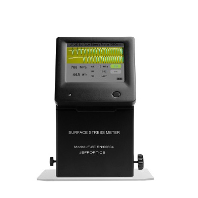
Choose the thermal interface deliberately
Software provides separate measure and set views, with different measurement interfaces for chemically and thermally tempered glass. That distinction matters when a laboratory handles both treatment routes and operators move between sample types.
Identify the specimen’s treatment before choosing the measuring interface. For a thermal-glass comparison, agree the surface-stress quantity and the relevant setup with the technical team. Keep the selected route in the laboratory record so later reviewers can understand which measurement was performed.
A broad instrument range does not resolve the method-selection question. Glass composition, optical condition, geometry and available measurement surface can change what is practical. If the intended sample does not match the proposed setup, request a model or tailored-configuration review with representative material.
Keep the optical inputs tied to the glass
The set view includes serial number, thermal-glass measurement selection, glass thickness, photoelastic coefficient, glass-core refractive index, and factor 1. These fields provide a specific reason to discuss the sample before ordering: the measurement setup includes glass-related inputs as well as instrument identification.
For a process-comparison task, retain the agreed settings with the specimen identity. If thickness, glass composition or an optical coefficient changes, make that change visible in the record. Otherwise, a difference attributed to a manufacturing trial could also contain a difference in the measurement setup.
Use the values and procedure agreed for the actual glass. Do not borrow coefficients from a different material simply because both samples are transparent or thermally treated. When material information is incomplete, send the available composition, treatment and sample details so Jeffoptics can evaluate the appropriate route.
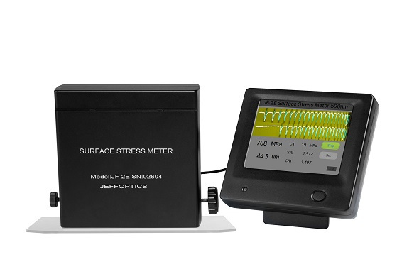
Use the adjustment controls to establish a working view
A prism is located at the bottom of the measuring instrument. The right adjustment knob controls the image, and the left adjustment knob controls the light-source position. The hinge-adjusted PDA provides a separate viewing arrangement for the operator.
These components matter when deciding whether the instrument can be used comfortably and consistently at the required location. Ask for a sample-based demonstration of the agreed measurement routine, including access, viewing and setup. The buyer should supply representative glass and the measurement objective; a special fixture or automated handling arrangement needs its own review.
The portable battery specification supports planning the instrument’s power provision. It does not establish operating time per charge or the number of samples that can be measured. Specify the expected session length and workload when reviewing the complete workflow.
Compare specimens before expanding the workflow
For a thermal-glass trial, begin with a defined set of specimens and matching measurement locations. Keep the treatment, thickness, selected interface and optical settings attached to each observation. Then decide whether the difference between specimens is meaningful for the engineering question.
If the next step is automated reporting or a connection to a factory system, define that requirement separately. The documented measure and set views do not establish automatic traceability, a cloud service or a production-control interface. Jeffoptics can evaluate software development and system integration once the desired record and decision are clear.
Questions about thermal-glass evaluation
Can JF-2E measure thermally tempered glass?
Yes. The model uses the optical waveguide effect for surface-stress measurement in thermally and chemically tempered glass, with different measurement interfaces. Actual sample and method fit still need evaluation.
Does the 100 µm depth range establish a thermal-glass compression-layer result?
It is a product depth-of-layer specification. Do not assume its chemical-glass interpretation applies to a thermal-glass decision; confirm the intended output and method for the treatment.
Why provide thickness and optical properties?
The set view includes thickness, photoelastic coefficient and glass-core refractive index. Agreeing those inputs helps keep the setup tied to the actual specimen.
Request a thermal-glass sample review
Send treatment and composition information, thickness, dimensions, curvature, surface condition, measuring locations, expected stress and the decision the measurement must support. Include the current procedure, workload, record needs, quantity, destination, budget and timing.
Request a Sample Review to evaluate JF-2E, another model or a tailored measurement and software approach.
Post time: Oct-28-2026